
Step 1
Good earthing (grounding) system according to IEC/BS EN 62305-3:2011 standard
E.5.4 Earth-termination system
E.5.4.1 General
(…) The LPS designer and the LPS installer should select suitable types of earth electrodes and should locate them at safe distances from entrances and exits of a structure and from the external conductive parts in the soil, such as cables, metal ducts, etc. Hence the LPS designer and the LPS installer should make special provisions for protection against dangerous step voltages in the vicinity of the earth-termination networks if they are installed in areas accessible to the public (see Clause 8).
The recommended value of the overall earth resistance of 10 Ω is fairly conservative in the case of structures in which direct equipotential bonding is applied. The resistance value should be as low as possible in every case but especially in the case of structures endangered by explosive material. Still the most important measure is equipotential bonding.
E.5.4.2.2 Type B arrangement
(…) The type B earth-termination system is preferred for meshed air-termination systems and for LPS with several down-conductors.
This type of arrangement comprises either a ring earth electrode external to the structure, in contact with the soil for at least 80% of its total length, or a foundation earth electrode.
E.5.4.3.2 Foundation earth electrodes
(…) A further problem arises from electrochemical corrosion due to galvanic currents. Steel in concrete has approximately the same galvanic potential in the electrochemical series as copper in soil. Therefore, when steel in concrete is connected to steel in soil, a driving galvanic voltage of approximately 1 V causes a corrosion current to flow through the soil and the wet concrete and dissolve steel in soil.
Earth electrodes in soil should use copper, copper coated steel or stainless steel conductors where these are connected to steel in concrete.
Step 2
Resistivity of soil
Resistivity measurements for good earthing (grounding) system according to IEEE Std 80-2000
(…) A number of measuring techniques are described in detail in IEEE Std 81-1983. The Wenner four-pin method, as shown in Figure below, is the most commonly used technique. In brief, four probes are driven into the earth along a straight line, at equal distances a apart, driven to a depth b. The voltage between the two inner (potential) electrodes is then measured and divided by the current between the two outer (current) electrodes to give a value of resistance R.
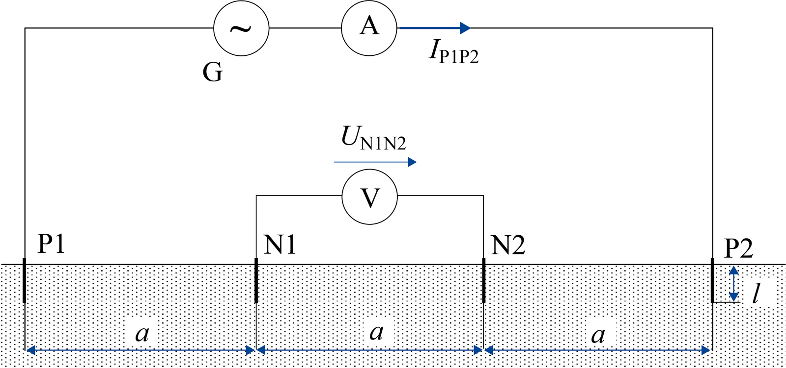
Wenner four-pin method
then for b « a:
where
ρa– is the apparent resistivity of the soil in Ωm
R – is the measured resistance (R=U/l) in Ω
a – is the distance between adjacent electrodes in m
b – is the depth of the electrodes in m
Resistivity for types of soil according to IEC 60364-5-54:2011
Nature of ground | Resistivity [Ωm] |
Marshy ground | From some units to 30 |
Malleable clay | 50 |
Clayey sand | 50 to 500 |
Soft limestone | 100 to 300 |
Granite and sandstone according to weathering | 1 500 to 10 000 |
Step 3
Good conductors and rods for earthing (grounding) system according to IEC/BS EN 62561-2:2012
Material, configuration and cross sectional area of earth electrodes
Material | Configuration | Cross sectional area a) | Recommended dimensions | |
Copper | Solid round | ≥ 150 h) | 14 mm diameter, if 250 µm minimum radial copper coating, with 99.9% copper content | |
Solid round | ≥ 50 | 8 mm diameter, if 250 µm minimum radial copper coating, with 99.9% copper content | ||
Solid round | ≥ 78 | 10 mm diameter, if 70 µm minimum radial copper coating, with 99.9% copper content | ||
Solid tape | ≥ 90 | 3 mm thickness, if 70 µm minimum radial copper coating, with 99.9% copper content | ||
a) Manufacturing tolerance – 3%
c) The copper shall be intrinsically bonded to the steel. The coating can be measured using an electronic coating measuring thickness instrument
h) In some countries, the cross sectional area may be reduced to 125 mm²
Step 4
Good cross section of earthing conductors according to IEEE Std 80-2000
11.2.2 Copper-clad steel
(…) Copper-clad steel is usually used for underground rods and occasionally for grounding grids, especially where theft is a problem. Use of copper, or to a lesser degree copper-clad steel, therefore assures that the integrity of an underground network will be maintained for years, so long as the conductors are of an adequate size and not damaged and the soil conditions are not corrosive to the material used.
Calculation of the cross section of earthing conductors based on IEEE standards 80-2000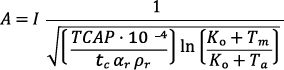
A – earthing conductor cross section in mm²
I – rms current in kA
TCAP – thermal capacity per unit volume in J/(cm³ °C)
tc – duration of current in s
αr – thermal coefficient of resistivity in 1/°C
ρr – resistivity of the ground conductor in mΩ-cm
Ko – 1/α o or (1/α r) – Tr in °C
Tm – maximum allowable temperature in °C
Ta – ambient temperature in °C
Samples cross section for copper clad conductors with different rms current in kA (I) and duration of current in s (tc)
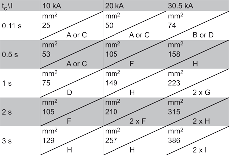
A) Φ 8 mm – 50 mm²
B) Φ 10 mm – 78 mm²
C) 20 x 3 mm – 60 mm²
D) 25 x 3 mm – 75 mm²
E) 30 x 3 mm – 90 mm²
F) 30.5 x 3 mm – 105 mm²
G) 30 x 4 mm – 120 mm²
H) 40 x 4 mm – 160 mm²
I) 40 x 5 mm – 200 mm²
Step 5
In the points from 4A to 4D there are the guidelines to design earthing (grounding) systems to the particular building facilities and structures according to the standards for these facilities.
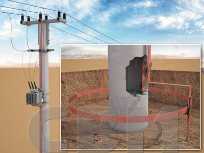
GROUNDING SYSTEM OF TRANSMISSION LINE TOWER (HV AND MV)
BS EN 50522:2010
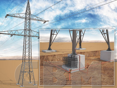
Resistance of the tower ground ring:
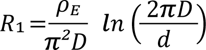
D = L/π– iameter of the ring in m
L – length of the ring tape in m
d – half the width of the tape in m
ρE – soil resistivity in Ωm
Resistance of the grounding rod with depth h: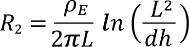
L – length of the grounding rod in m
d – diameter of the grounding rod in m
ρE – soil resistivity in Ωm
Resistance of the grounding system: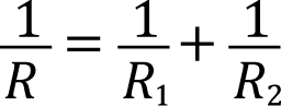
As the tapes and vertical rods of the external rods system are connected with the steel immersed in the stop footing concrete of the antenna tower, they have to made of precious metals, such as copper-bonded steel, stainless steel or solid copper. Copper-bonded steel materials were applied in the presented installation. This allowed to decrease the grounding (earthing) costs by 45% comparing to the stainless steel or solid copper.
POWER STATION (HV and MV)
IEEE Std 80-2000
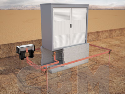
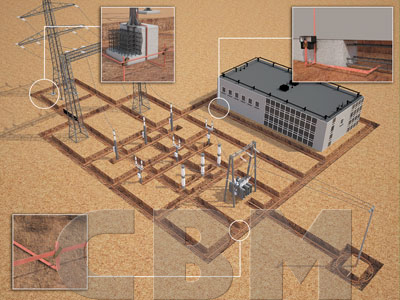
14.3 Schwarzs equations
(…) Schwarz developed the following set of equations to determine the total resistance of a grounding system in a homogeneous soil consisting of horizontal (grid) and vertical (rods) electrodes. Schwarz’s equations extended accepted equations for a straight horizontal wire to represent the ground resistance, R1, of a grid consisting of crisscrossing conductors, and a sphere embedded in the earth to represent ground rods, R2. He also introduced an equation for the mutual ground resistance Rm between the grid and rod bed.
Schwarz used the following equation introduced by Sunde and Rüdenberg to combine the resistance of the grid, rods, and mutual ground resistance to calculate the total system resistance, Rg.
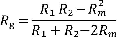
R1 – ground resistance of grid conductors in Ω
R2 – ground resistance of all ground rods in Ω
Rm – mutual ground resistance between the group of grid conductors, R1, and group of ground rods, R2 in Ω
Ground resistance of the grid

ρE – is the soil resistivity in Ωm
Lc – is the total length of all connected grid conductors in m
α ‘- is for conductors buried at depth h in m
2α – is the diameter of conductor in m
S – is the area covered by conductors in m2
k1, k2 – are the coefficients [see Figure 1 and 2]

Lr – is the length of each rod in m
2b – is the diameter of rod in m
nR – number of rods placed in area S

A – is the length of the grid, B – is the width of the grid,
A/B – is the length-to-width ratio, h – is the depth of the grounding grid
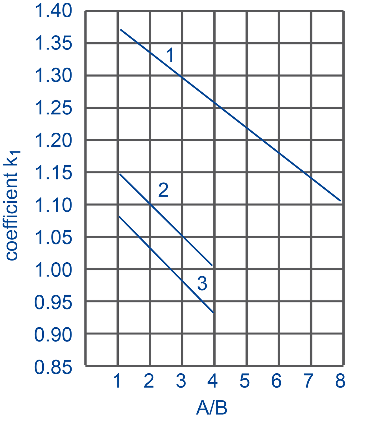
curve 1 for depth h = 0
y1 = – 0.04x + 1.41
curve 2 for depth 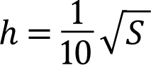
y2 = – 0.05x + 1.20
curve 3 for depth 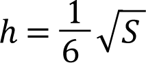
y3 = – 0.05x + 1.13
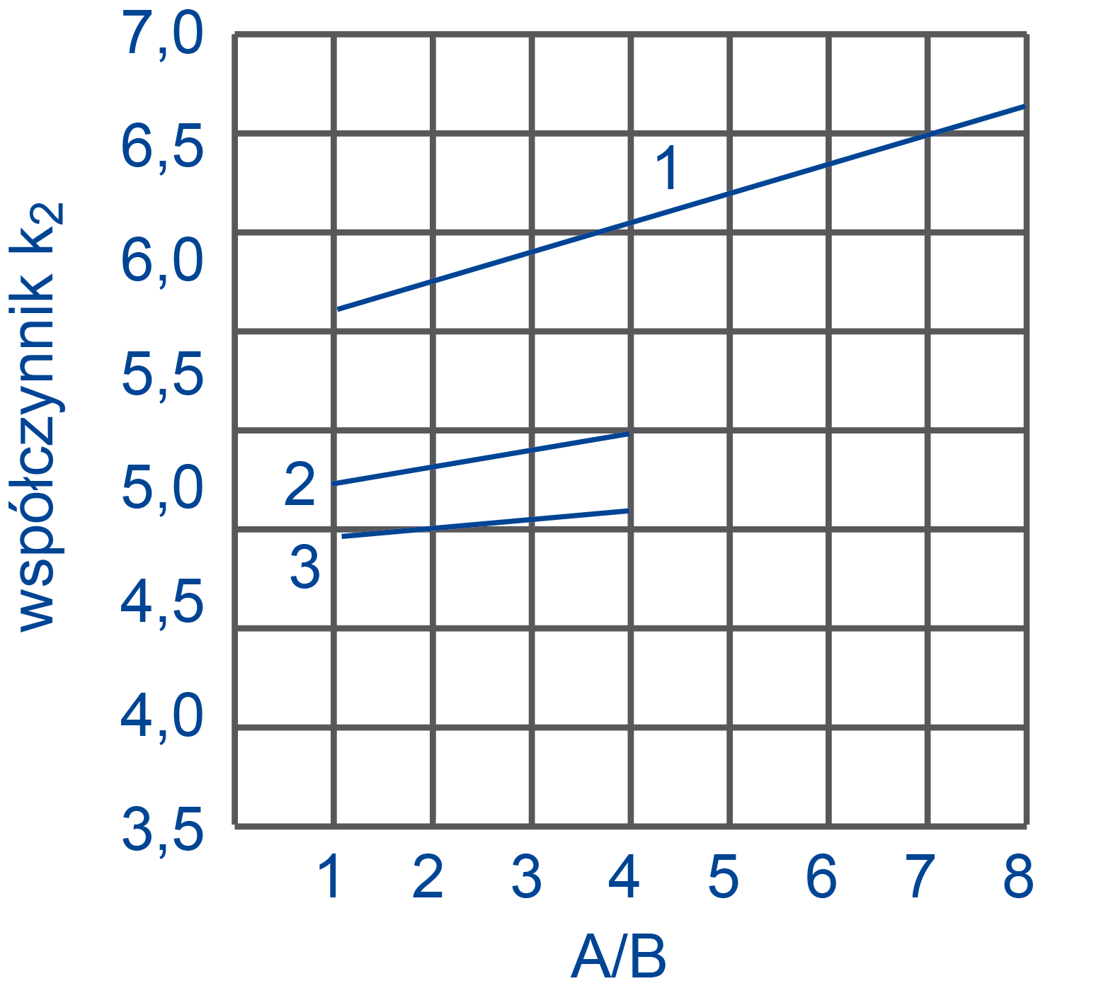
curve 1 for depth h = 0
y1 = 0.15x + 5.50
curve 2 for depth
y2 = 0.10x + 4.68
curve 3 for depth
y3 = – 0.05x + 4.40
As the tapes and vertical rods of the external rods system are connected with the steel immersed in the stop footing concrete of the antenna tower, they have to made of precious metals, such as copper-bonded steel, stainless steel or solid copper. Copper-bonded steel materials were applied in the presented installation. This allowed to decrease the grounding (earthing) costs by 45% comparing to the stainless steel or solid copper.
GROUNDING SYSTEM OF LV TRANSMISSION LINE TELECOMMUNICATION TOWERS
HD 60364-5-54
Resistance of the tower ground ring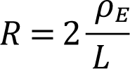
L – length of the ring tape in m
ρE – soil resistivity in Ωm
Resistance of the grounding rod: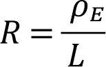
L – length of the grounding rod in m
ρE – soil resistivity in Ωm
Resistance of the grounding system:
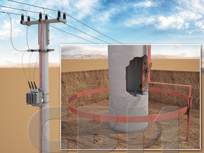
As the tapes and vertical rods of the external rods system are connected with the steel immersed in the stop footing concrete of the antenna tower, they have to made of precious metals, such as copper-bonded steel, stainless steel or solid copper. Copper-bonded steel materials were applied in the presented installation. This allowed to decrease the grounding (earthing) costs by 45% comparing to the stainless steel or solid copper.
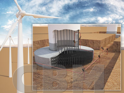
GROUNDING SYSTEM OF HIGH-VOLTAGE LINES WIND TURBINE FACILITIES CONSTRUCTION
(IEC) BS EN 62305-3
E.5.4 Earth termination system
E.5.4.1 General
(…) the LPS designer and the LPS installer should make special provisions for protection against dangerous step voltages in the vicinity of the earth-termination networks if they are installed in areas accessible to the public (see Clause 8).
The recommended value of the overall earth resistance of 10 Ω is fairly conservative in the case of structures in which direct equipotential bonding is applied. The resistance value should be as low as possible in every case but especially in the case of structures endangered by explosive material. Still the most important measure is equipotential bonding.
E.5.4.2 Types of earth electrode arrangements
E.5.4.2.1 Type A arrangement
(…) This type of arrangement comprises horizontal or vertical electrodes connected to each down-conductor.
Where there is a ring conductor, which interconnects the down-conductors, in contact with the soil the earth electrode arrangement is still classified as the type A if the ring conductor is in contact with the soil for less than 80% of its length.
E.5.2.2 Type B arrangement
(…) This type of arrangement comprises either a ring earth electrode external to the structure, in contact with the soil for at least 80% of its total length, or a foundation earth electrode.
For bare soild rock, only the type B earthing arrangement is recommended.
As the tapes and vertical rods of the external rods system are connected with the steel immersed in the stop footing concrete of the antenna tower, they have to made of precious metals, such as copper-bonded steel, stainless steel or solid copper. Copper-bonded steel materials were applied in the presented installation. This allowed to decrease the grounding (earthing) costs by 45% comparing to the stainless steel or solid copper.